
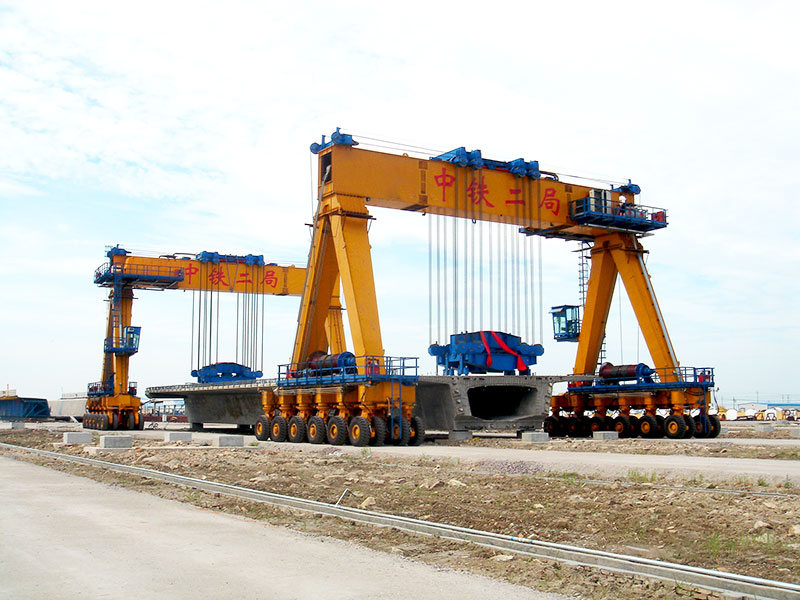
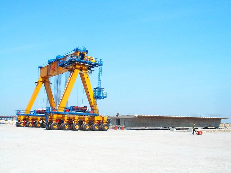
In the sector of heavy civil engineering, the demand for longer bridge spans has pushed the manufacturing of precast concrete beams to extreme dimensions. It is now common to see precast girders exceeding 40 or 50 meters in length. While these dimensions optimize structural performance and reduce the number of onsite piers, they present a massive logistical hurdle: how to move a 150-ton, 50-meter “rigid” body through a casting yard without causing structural cracking or equipment failure.
The solution typically involves the coordinated use of two or more rubber-tired straddle cranes. However, moving an ultra-long beam with two independent machines is not as simple as driving two trucks in tandem. It requires a sophisticated integration of mechanical engineering, electronic synchronization, and rigorous site management.
The Fundamental Risk: Torsional Stress and Rigidity
The primary technical challenge in lifting ultra-long concrete beams is their vulnerability to torsion. While precast beams are designed to handle immense vertical loads once installed, they are surprisingly sensitive to twisting during transit.
If two straddle cranes are lifting a 50-meter beam and one crane travels slightly faster than the other, or if one side lifts higher by just a few centimeters, the beam becomes a giant lever. The resulting “racking” force can induce shear stresses that the concrete is not reinforced to handle. Without precise synchronization, you risk hairline fractures or “latent damage” that might not be visible until the beam is under full load in a bridge structure.
Strategy 1: Integrated Control Systems (Electronic Coupling)
In modern operations, the era of relying solely on two operators communicating via radio is over. The margin for error is too slim. Instead, technical strategies now center on Electronic Synchronization via PLC (Programmable Logic Controller).
Rather than two independent machines, the rubber tyred cranes are linked into a single functional unit through an industrial wireless mesh network. One crane is designated as the primary unit, while the second acts as a secondary unit that mirrors every input.
-
Velocity Synchronization: The system monitors the wheel encoders of both cranes. If the primary crane encounters a slight incline and its motor torque increases, the secondary crane receives this data in milliseconds and adjusts its output to match the exact linear velocity.
-
Vertical Alignment: Laser distance sensors or high-precision ultrasonic transducers are mounted on the hoist frames. These sensors continuously measure the distance from the hook to the ground. If the deviation between the two cranes exceeds a preset threshold (often as small as 10mm), the system automatically throttles the faster hoist to re-level the load.
Strategy 2: Hydraulic Load Balancing and Three-Point Suspension
A common mistake in heavy lifting is assuming that four lifting points (two per crane) provide more stability. In reality, a four-point lift on a rigid object is “statically indeterminate.” If the ground is not perfectly flat, one of those four points will inevitably carry more weight than the others, potentially overloading a single sling or the concrete anchor point.
To solve this, engineers implement a Three-Point Suspension Strategy:
-
On one straddle crane, the two hoisting winches operate independently.
-
On the second crane, the two winches are hydraulically or electronically linked to act as a single pivoting “virtual point.”
-
This allows the beam to “settle” into its natural equilibrium during travel, much like a three-legged stool that never wobbles on uneven ground.
Furthermore, Hydraulic Equalization Cylinders are often integrated into the rigging. If one crane hits a minor bump, the hydraulic fluid shifts between cylinders to maintain a constant tension on the slings, preventing sudden “shock loads” from snapping the rigging or damaging the beam.
Strategy 3: Dynamic Motion Control (The S-Curve Algorithm)
Inertia is a significant enemy when moving 100+ tons of concrete. If a 100 ton gantry crane starts or stops abruptly, the beam will swing. This pendulum effect creates horizontal forces that the crane’s telescopic legs are not designed to absorb in high magnitudes.
To mitigate this, the control software utilizes S-Curve Acceleration Profiles. Instead of a sudden jump in speed, the motor controller follows a “bell curve” logic:
-
The Tapered Start: The cranes begin moving at a near-invisible crawl, gradually increasing torque until the static friction of the tires is overcome.
-
Controlled Deceleration: Braking is the most dangerous phase. The system prevents “hard braking” by using regenerative motor braking to slowly bleed off kinetic energy. This ensures that the beam and the cranes come to a halt as a single, motionless mass, eliminating the risk of the load swinging into the crane structure.
Strategy 4: Civil Engineering of the Travel Path
A straddle crane lift is only as reliable as the surface beneath its tires. For ultra-long beams, the “Road Map” is just as important as the crane itself.
Ground Bearing Capacity (GBC): Straddle cranes exert massive point loads. Before a synchronized lift, the travel path must be professionally surveyed. In many yards, this involves a reinforced concrete “runway” or highly compacted gravel layers. If one crane’s tires sink by even 2 centimeters more than the other’s due to soft soil, the synchronization system will be forced to work overtime to compensate for the tilt, which adds unnecessary stress to the mechanical components.
Grade and Cross-Fall: For synchronized lifts, the path must be nearly level. A longitudinal grade of more than 1% or a cross-fall (side-to-side tilt) of more than 0.5% can shift the center of gravity of an ultra-long beam outside of its “safe zone,” increasing the risk of a tip-over.
Strategy 5: Rigging Geometry and Spreader Beams
For ultra-long beams, the angle of the lifting slings (the “sling angle”) is critical. If the slings pull inward at too sharp an angle, they create a compressive force on the top of the beam that can cause it to buckle.
To prevent this, Modular Spreader Beams are used. These steel frames ensure that the lifting force on the concrete is purely vertical. When using multi-crane synchronization, these spreader beams often include “ball-and-socket” joints or swivels. These allow for minor deviations in crane alignment – such as if one crane is slightly offset to the left of the other – without twisting the concrete girder.
Strategy 6: The “Human-in-the-Loop” Protocol
Even with advanced PLC synchronization, the human element remains the final fail-safe. A synchronized lift requires a specific crew hierarchy:
-
The Lift Director: A single person who has a bird’s-eye view of both cranes. They are the only voice allowed on the primary radio channel.
-
Corner Spotters: Four individuals stationed at the leading and trailing “corners” of the operation. Their sole job is to monitor tire-to-path alignment and obstacle clearance.
-
The Emergency Stop (E-Stop) Chain: In a synchronized setup, the E-Stops of both gantry cranes are linked. If any spotter or operator hits an E-Stop, both machines lock down simultaneously. This prevents one crane from continuing to move while the other is stationary, which would otherwise result in a catastrophic pull-over.
Conclusion: Efficiency Through Precision
Multi-straddle-crane synchronization is a testament to how far industrial lifting has come. By moving away from manual “guesswork” and adopting integrated electronic controls, hydraulic balancing, and rigorous path planning, precast yards can handle longer and heavier beams than ever before.
The goal of these technical strategies is to turn a high-risk operation into a repeatable, “boring” process. When a 50-meter concrete beam is transported across a yard with zero visible sway and zero structural stress, it is the result of invisible engineering working in perfect harmony. For the modern content strategist or engineer, documenting these protocols is not just about showing power—it’s about demonstrating a commitment to structural integrity and operational safety.